01
Design
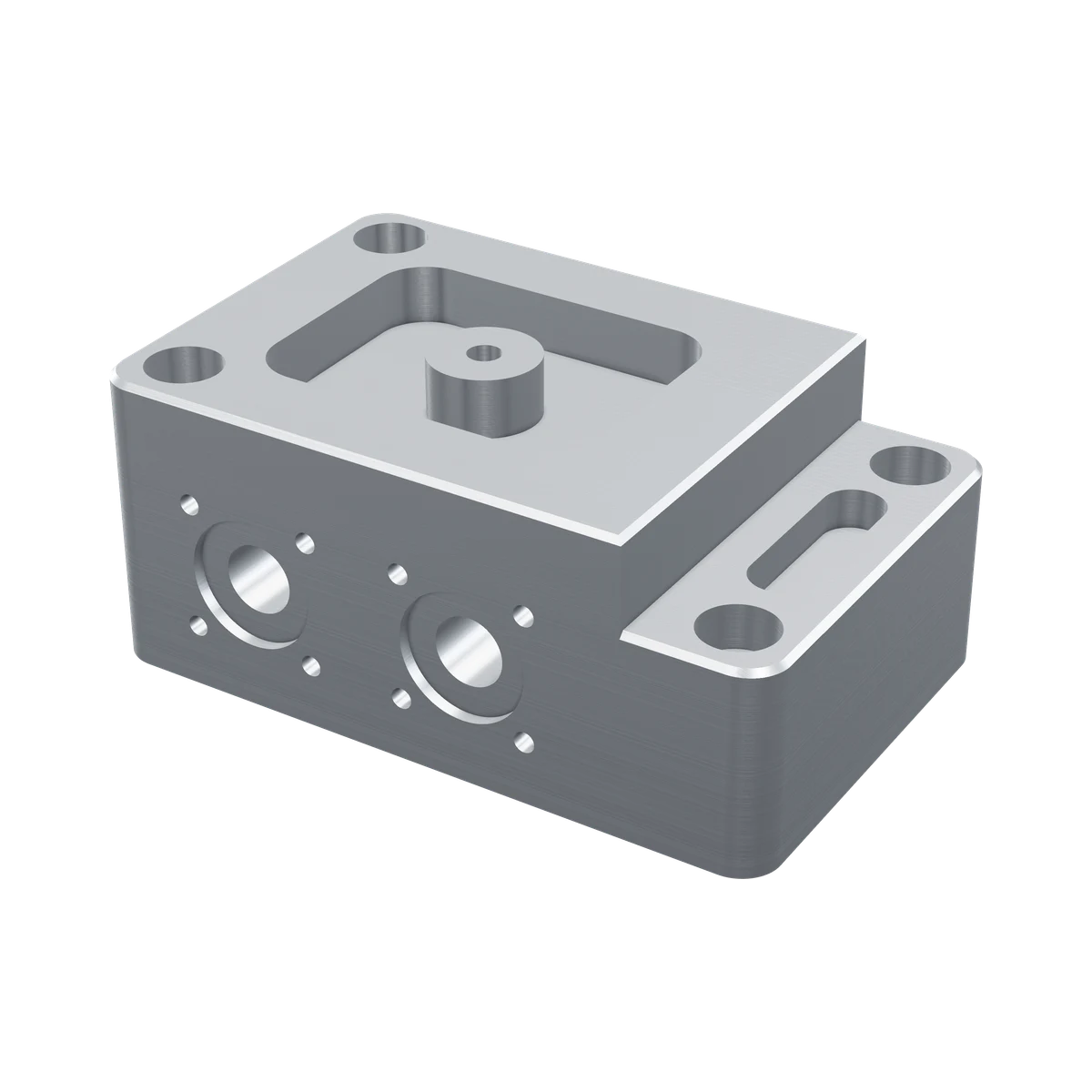
Block, corners, pocket and holes, one feature at a time, each in a history you can edit.
Design · Simulate · ManufactureAI Agent
CAD, CAE, CAM and an AI Agent in one desktop platform. Tell the Agent what you need and watch one part go from design to analysis, milling program and drawing.
Real nForme geometry and results, rendered live
Windows desktopCloud data management · coming
The platform
01
Block, corners, pocket and holes, one feature at a time, each in a history you can edit.
02
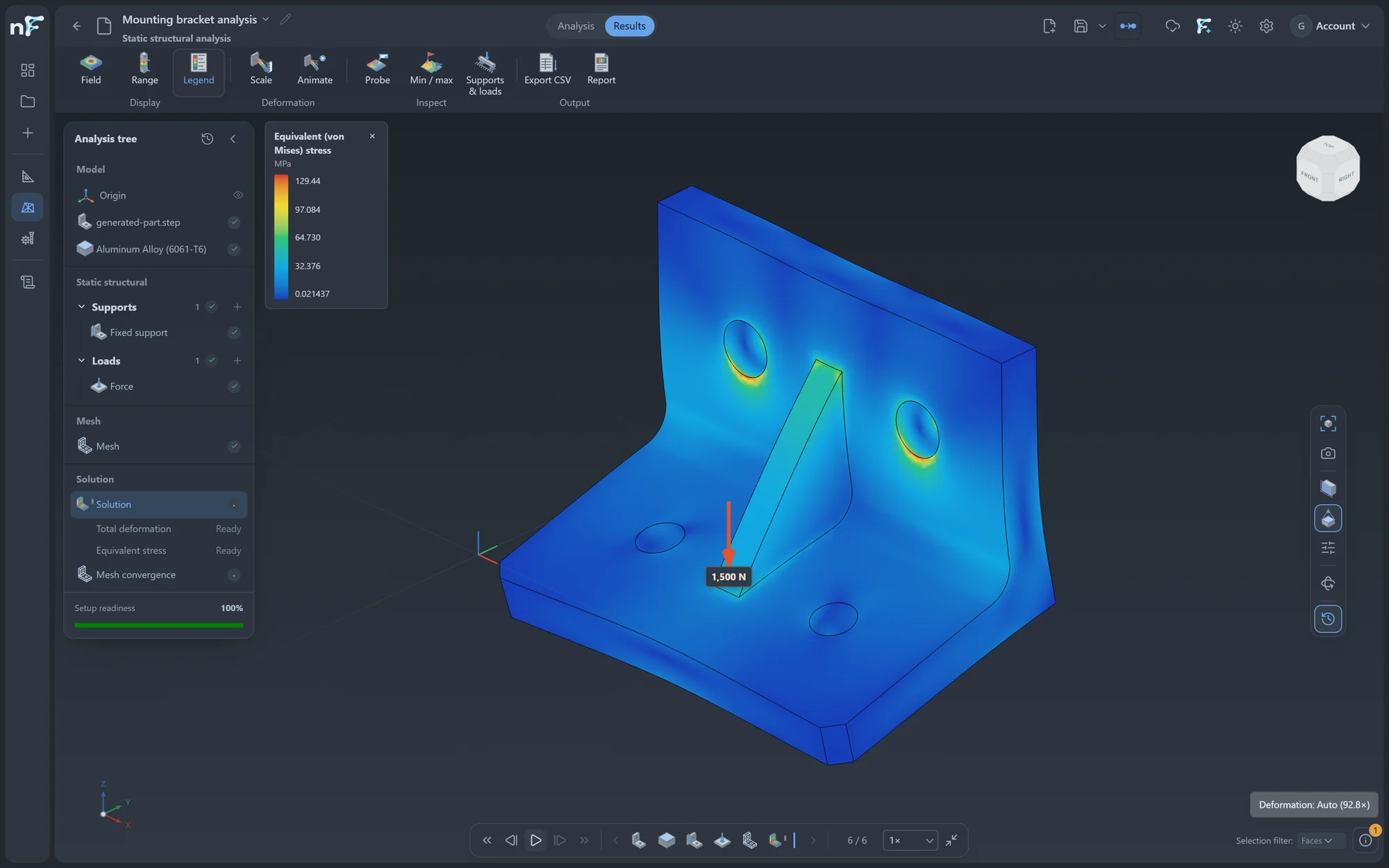
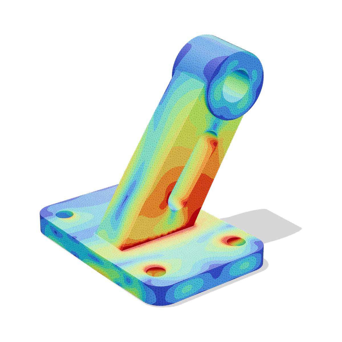
2 kN on the pocket floor, held at the four holes: stress read on the very part you designed.
03
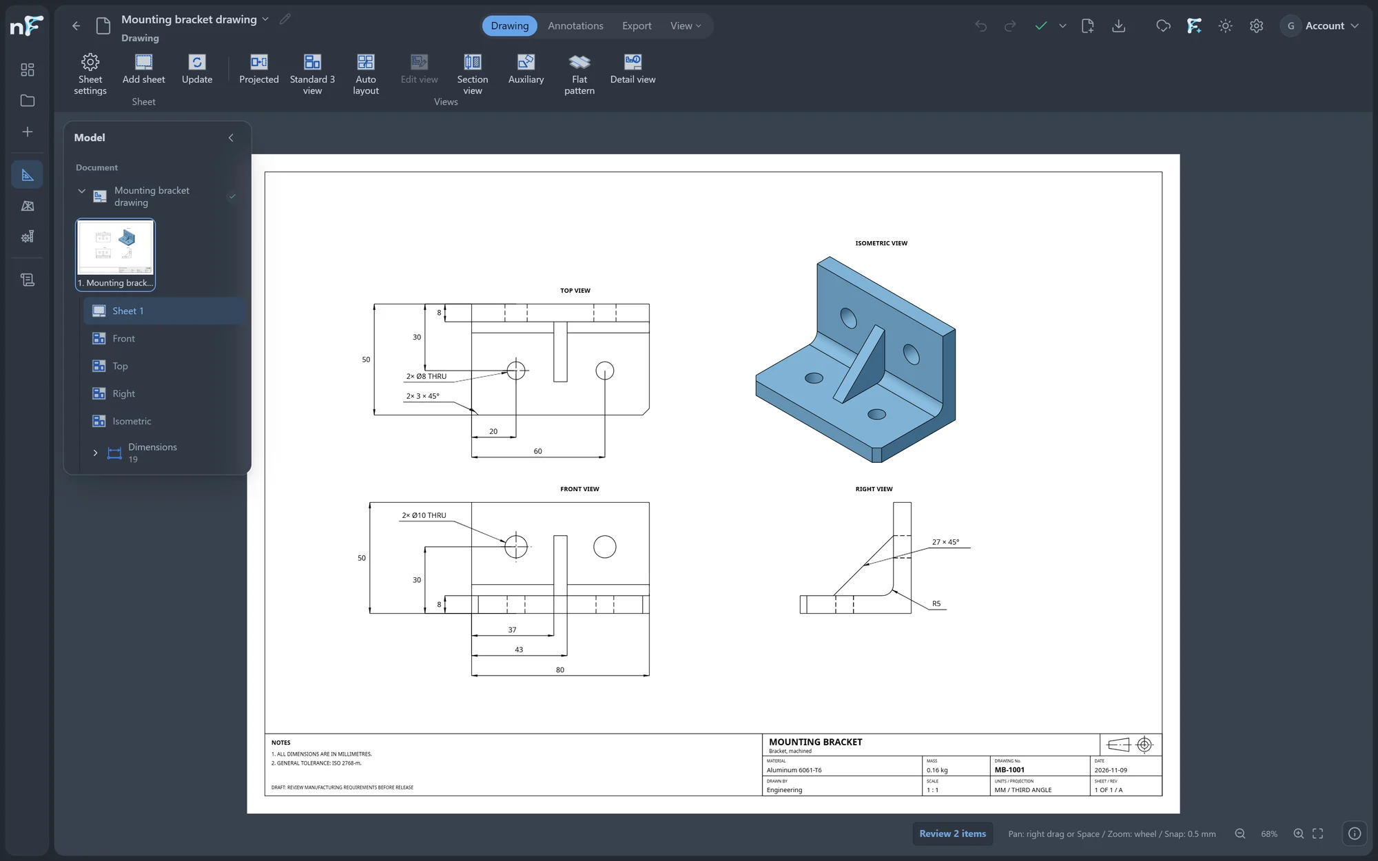
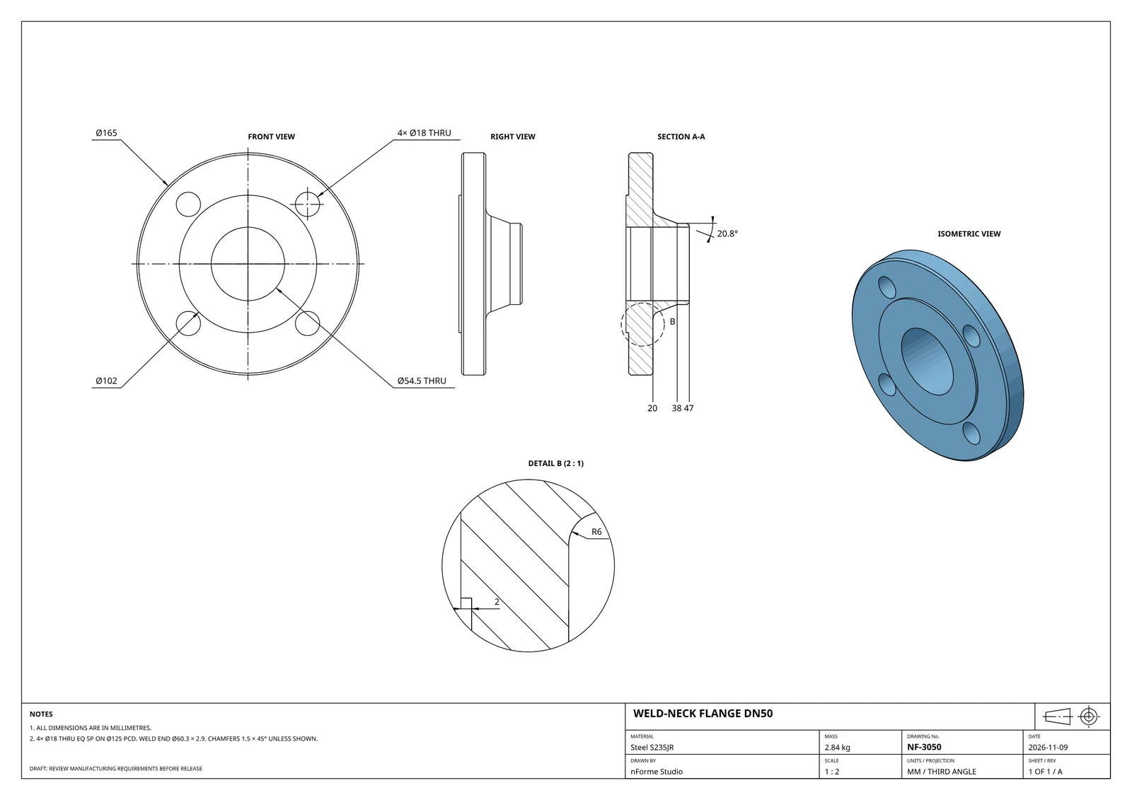
The part becomes its lines, then a dimensioned sheet.
04
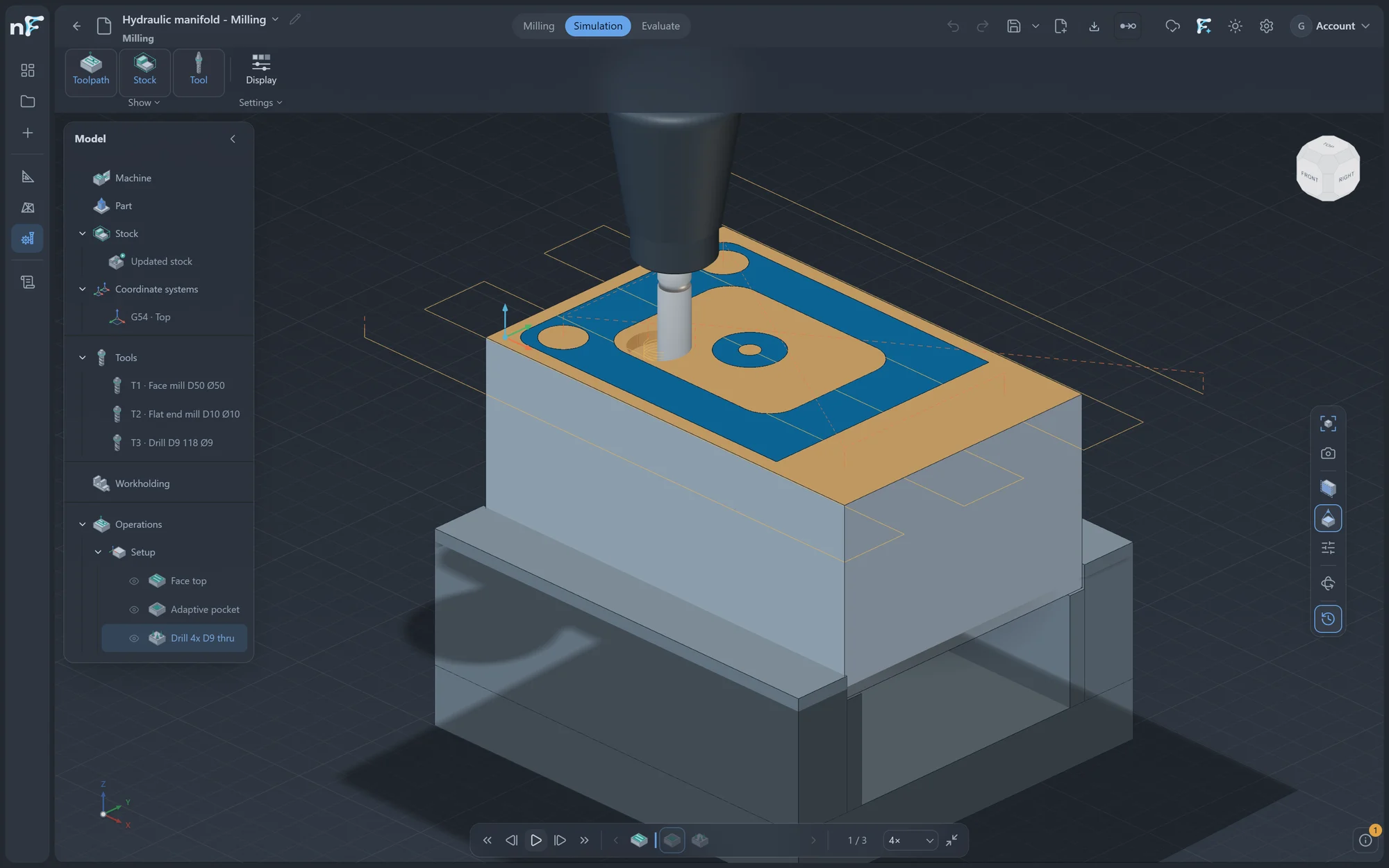
Into the vise, toolpaths calculated and simulated before the machine.
Real screens from nForme Studio
Each discipline has its own workbench, with the same ribbon, history tree and 3D view. Change the job without changing how you work.
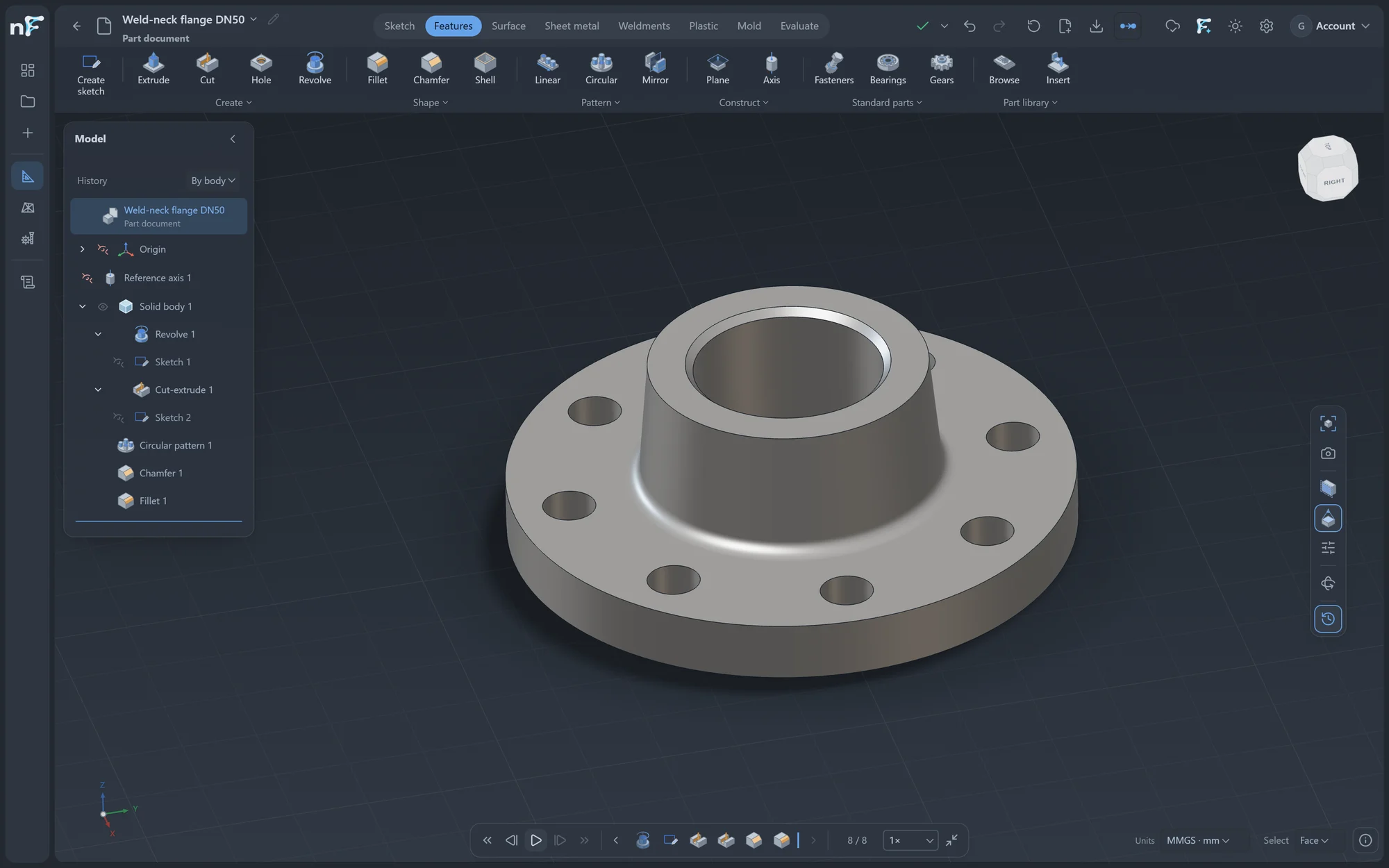
01 · Design
Every feature is checked for valid geometry before it is saved, and every part exports to STEP. This planetary set was built in nForme and turns at its true ratios.
Constrained sketches, parametric solid and surface features, patterns and a full history tree.
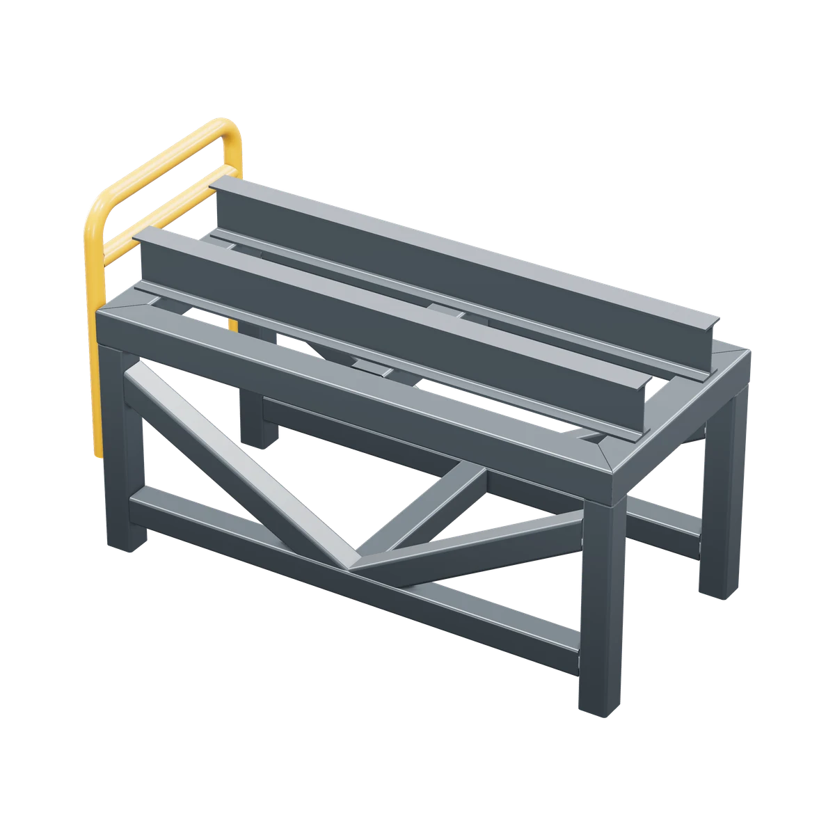
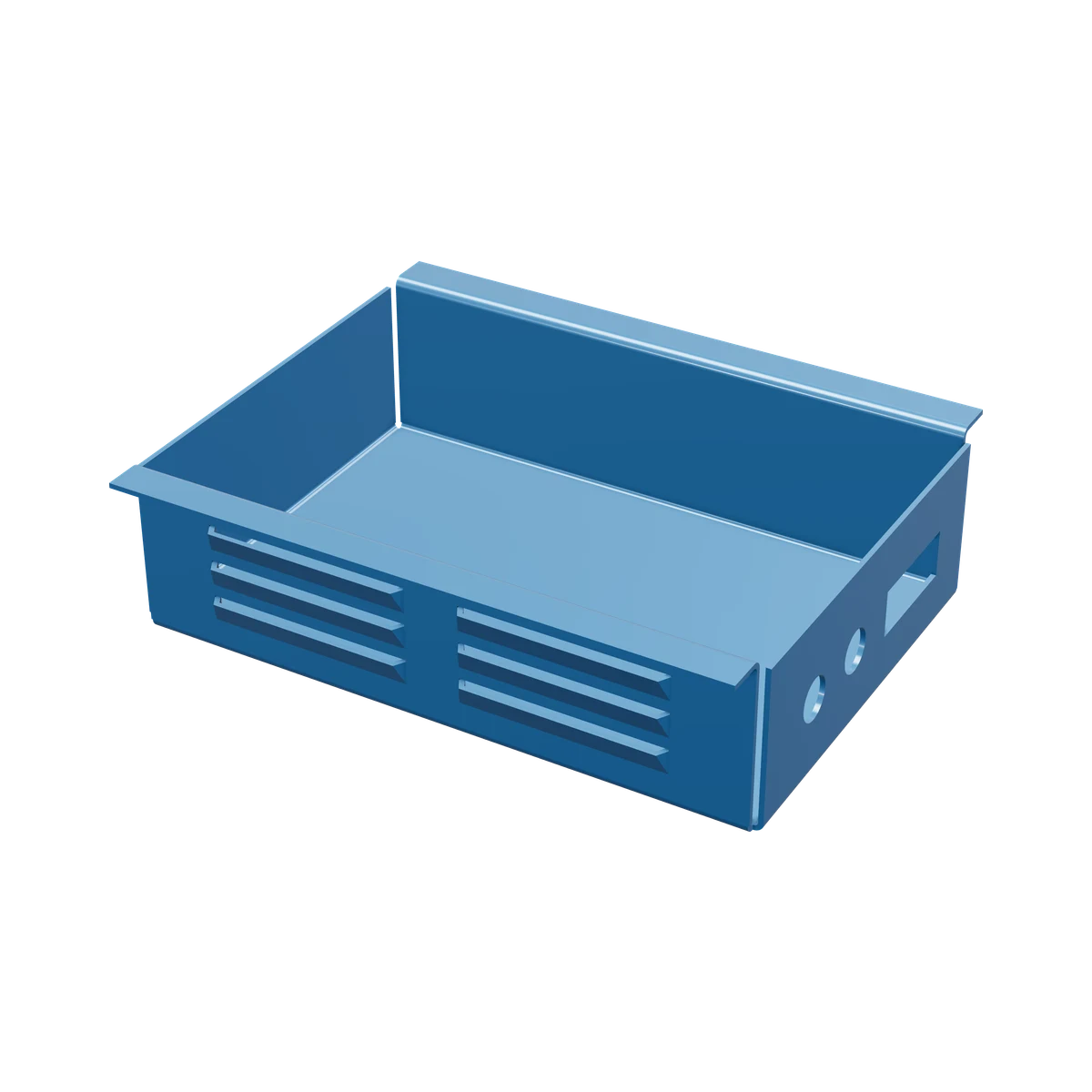
Folded parts with flat patterns, and welded frames from structural profiles.
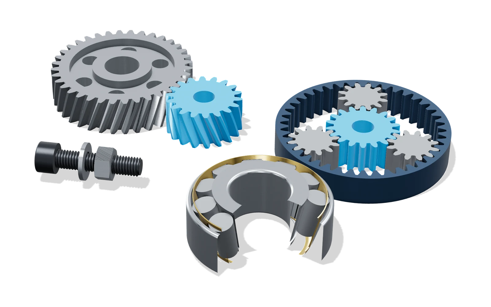
Fasteners, bearings, threads, gears and more, generated to size.
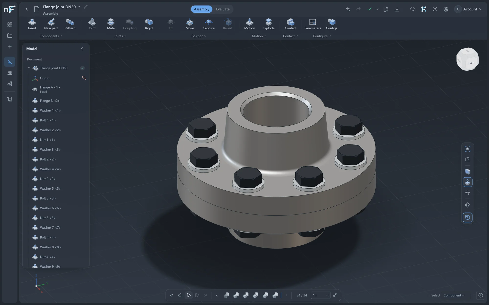
Place components, mate them and explode the assembly.
Projected, section and auxiliary views, dimensions and annotations on standard sheets.
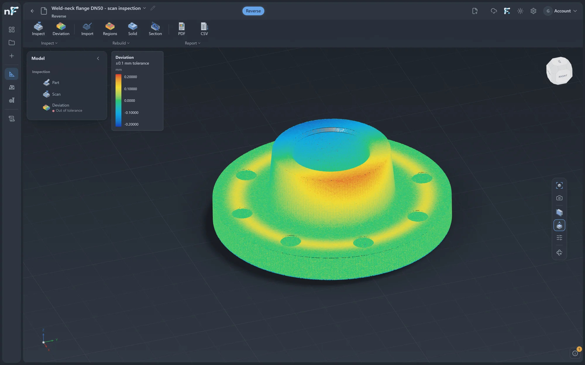
Bring in a scan, find its planes, cylinders and cones, and rebuild the part.
Assembly
A bearing housing on a stepped shaft: housing, tapered roller bearing from the standard parts, cap and screws, exploded along the shaft.
Drawing
Projected views, section A-A, a 2:1 detail, dimensions and a shaded isometric on an A3 sheet, exported to PDF and DXF.
Reverse engineering
A real scan of 4 million points, sorted into 317 planes, cylinders, cones, spheres and free-form surfaces.
Scan: Artec 3D, CC BY 3.0
02 · Simulate
Mesh, solve and read the results on the very model you designed, without handing it to another program. Every result here is a real solve.
Linear static
Al 6061-T6 · four flange bolt holes fixed · 9 kN on the boss bore · peak deflection 0.35 mm, shown ×26
Modal
Al 6061-T6 · base bolt holes fixed · first six modes 1066 to 3097 Hz · twisting mode, amplitude exaggerated
Transient thermal
Al 6061-T6 · 40 W on a 40 × 40 mm pad · 25 W/m²K to 20 °C air · 31.5 to 39.9 °C at 25 min
Loads, supports and materials in; displacement, stress and safety factor out.
Natural frequencies and the mode shapes behind them.
Response to a load that cycles across a range of frequencies.
Steady and transient heat transfer, and the solved temperature carried into a stress study.
03 · Machine
This is the CAM program's own output: a 10 mm end mill clearing the pocket round its island, pass by pass, along the path nForme calculated.
Stock, work offsets and a shop tool table with real cutter geometry.
Facing, adaptive pocketing, contours, drilling and 3D operations.
Watch material come away and check the tool's motion before it reaches the machine.
Made in nForme
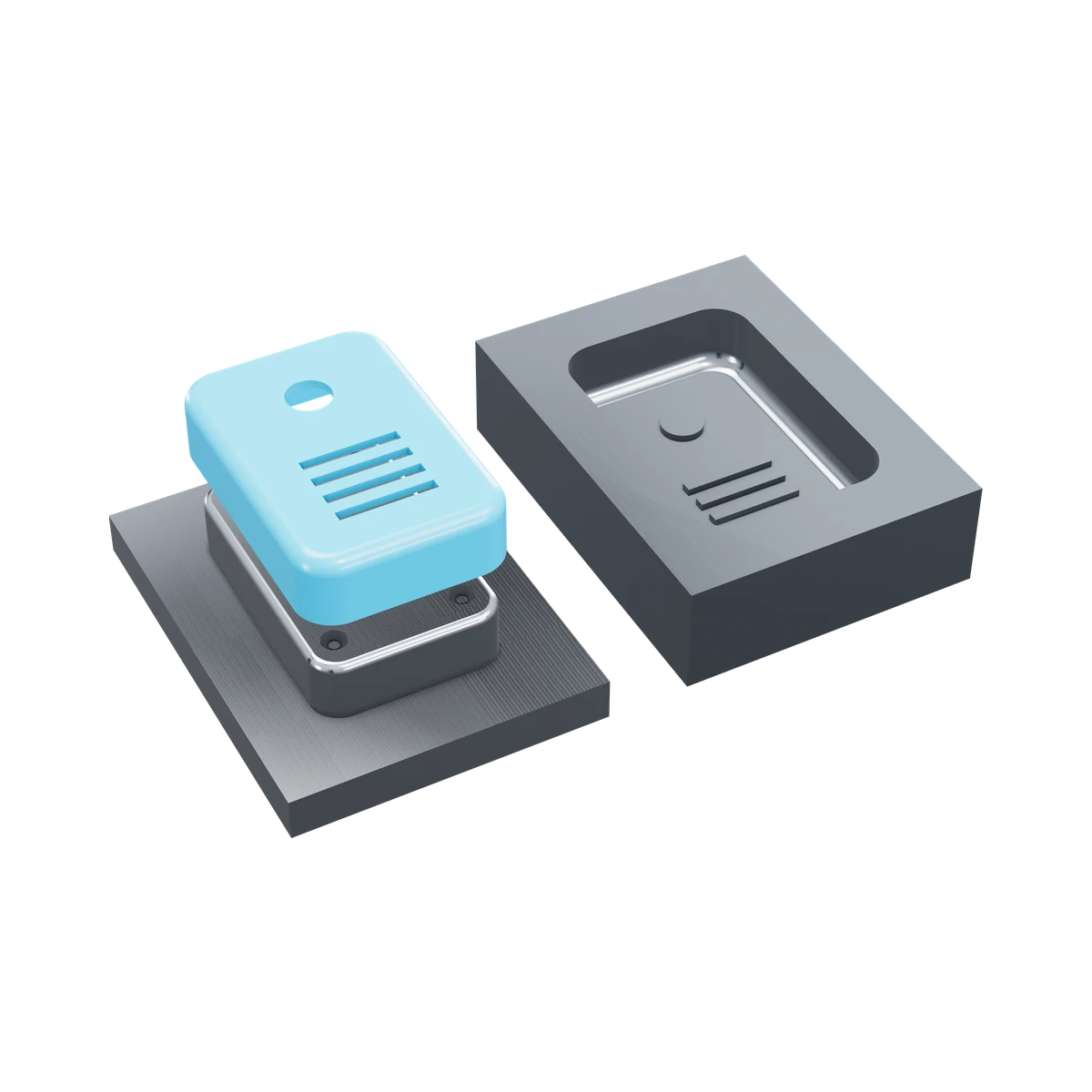
From standard parts to welded frames, mold tooling and sheet metal, every model here was built with nForme's CAD tools.
Case
The MiniCNC-00 full gantry: base plate, side walls, T-slot table, SBR16 rails, ball screws, NEMA 23 motors and the spindle, placed, mated and grouped in the Assembly workbench.
Desktop · Agent · Cloud
The heavy work runs on your workstation; projects, versions and sharing will be managed in the cloud, so a team works from one set of data.
01
A Windows app that uses your workstation's full power and keeps documents on your disk, for large models and heavy analysis.
02
Cloud data management: projects, versions and sharing across machines and teammates, so everyone works from the same data.
03
One assistant across every workbench, driven in plain language, from design and analysis to milling programs and drawings.
A
Import and export STEP to work alongside the tools you already use.
B
Parts, assemblies, drawings, analyses and toolpaths live in one project and link to each other.
C
Website, legal documents and support in both languages.
D
Every installer lists its version, size and SHA-256 so you can check the file yourself.
Next
Vary a design's dimensions against your engineering targets and limits.
Find where material is needed inside a design space, and where it is not.
Download
The preview is in review. When it is ready, this page shows its version, file size, SHA-256 and release notes.
FAQ
nForme is a Windows desktop app. Cloud data management (projects, versions and sharing across machines) is coming.
Part design, assemblies, drawings, reverse engineering, structural and thermal analysis, CNC milling and the AI Agent. Shape and topology optimization are coming next.
The installer is published on this page once it has been reviewed, with its version, size and SHA-256 so you can check the file.
Yes. Screens are captured from nForme Studio, every model is built with nForme's CAD tools, the analysis results come from real solves, and the toolpath is the CAM program's own output. No AI-generated imagery is used.
Support and GPL/LGPL source requests: support@nformestudio.com. Personal data: privacy@nformestudio.com.